Note
This page was generated from tut//3-Renderers//3.1-Introduction-to-QRenderers.ipynb.
Introduction to QRenderers#
For convenience, let’s begin by enabling automatic reloading of modules when they change.
[1]:
%load_ext autoreload
%autoreload 2
Import Qiskit Metal#
[2]:
import qiskit_metal as metal
from qiskit_metal import designs, draw
from qiskit_metal import MetalGUI, Dict, Headings

from qiskit_metal.qlibrary.qubits.transmon_pocket import TransmonPocket
from qiskit_metal.qlibrary.qubits.transmon_cross import TransmonCross

from qiskit_metal.renderers.renderer_gds.gds_renderer import QGDSRenderer
[3]:
Headings.h1('The default_options in a QComponent are different than the default_options in QRenderers.')
The default_options in a QComponent are different than the default_options in QRenderers.

[4]:
TransmonPocket.default_options
[4]:
{'chip': 'main',
 'pos_x': '0um',
 'pos_y': '0um',
 'pad_gap': '30um',
 'inductor_width': '20um',
 'pad_width': '455um',
 'pad_height': '90um',
 'pocket_width': '650um',
 'pocket_height': '650um',
 'orientation': '0',
 '_default_connection_pads': {'pad_gap': '15um',
  'pad_width': '125um',
  'pad_height': '30um',
  'pad_cpw_shift': '5um',
  'pad_cpw_extent': '25um',
  'cpw_width': 'cpw_width',
  'cpw_gap': 'cpw_gap',
  'cpw_extend': '100um',
  'pocket_extent': '5um',
  'pocket_rise': '65um',
  'loc_W': '+1',
  'loc_H': '+1'}}
[5]:
QGDSRenderer.default_options
[5]:
{'short_segments_to_not_fillet': 'True',
 'check_short_segments_by_scaling_fillet': '2.0',
 'gds_unit': '1',
 'ground_plane': 'True',
 'negative_mask': {'main': []},
 'corners': 'circular bend',
 'tolerance': '0.00001',
 'precision': '0.000000001',
 'width_LineString': '10um',
 'path_filename': '../resources/Fake_Junctions.GDS',
 'junction_pad_overlap': '5um',
 'max_points': '199',
 'cheese': {'datatype': '100',
  'shape': '0',
  'cheese_0_x': '25um',
  'cheese_0_y': '25um',
  'cheese_1_radius': '100um',
  'view_in_file': {'main': {1: True}},
  'delta_x': '100um',
  'delta_y': '100um',
  'edge_nocheese': '200um'},
 'no_cheese': {'datatype': '99',
  'buffer': '25um',
  'cap_style': '2',
  'join_style': '2',
  'view_in_file': {'main': {1: True}}},
 'bounding_box_scale_x': '1.2',
 'bounding_box_scale_y': '1.2'}
A renderer needs to inherent from QRenderer#
For Example, QGDSRender inherents from QRenderer.
When any QRenderer is registered within QDesign, the QRenderer instance has options, which hold the latest set of values for default_options. The GUI can also update these options.
An example of updating options is further below in this notebook.
A user can customize things two ways#
Directly update the options that originated from default_options, for either QComponent or QRenderer.
Pass options to a QComponent which will be placed in a QGeometry table, then used by QRenderer.
How to get options from QRenderer to be placed within the QGeometry table?#
We set this up so that older QComponents can be agnostic of newer QRenderers.
An example of this below is gds_cell_name='FakeJunction_01'. This is passed through to QGeometry, when a QComponent is instantiated. The QGDSRenderer has a default, which is not editable during run-time, but can be customized when a QComponent is instantiated.
[6]:
Headings.h1('How does a QRenderer get registered within QDesign?')
How does a QRenderer get registered within QDesign?
By default, QRenderers are registered within QDesign during init QDesign#
renderers_to_load has the name of the QRenderer (key), class name (value), and path (value).Presently, GDS and Ansys QRenderers are registered during init.
[7]:
design = designs.DesignPlanar()
[8]:
# Use GDS QRenderer for remaining examples.  Can do similar things with Ansys QRenderer.

#an_ansys = design._renderers['ansys']
#an_ansys = design._renderers.ansys

#a_gds = design._renderers['gds']
a_gds = design._renderers.gds
[9]:
gui = MetalGUI(design)
design.overwrite_enabled = True
[10]:
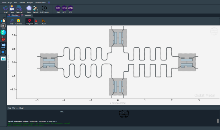
Headings.h1('Populate QDesign to demonstrate exporting to GDS format.')
Populate QDesign to demonstrate exporting to GDS format.
[11]:
from qiskit_metal.qlibrary.qubits.transmon_pocket import TransmonPocket

# Allow running the same cell here multiple times to overwrite changes
design.overwrite_enabled = True

## Custom options for all the transmons
options = dict(
    # Some options we want to modify from the deafults
    # (see below for defaults)
    pad_width = '425 um',
    pad_gap = '80 um',
    pocket_height = '650um',
    # Adding 4 connectors (see below for defaults)
    connection_pads=dict(
        a = dict(loc_W=+1,loc_H=+1),
        b = dict(loc_W=-1,loc_H=+1, pad_height='30um'),
        c = dict(loc_W=+1,loc_H=-1, pad_width='200um'),
        d = dict(loc_W=-1,loc_H=-1, pad_height='50um')
    )
)
Note:#
[12]:
## Create 4 TransmonPockets

q1 = TransmonPocket(design, 'Q1', options = dict(
    pos_x='+2.55mm', pos_y='+0.0mm', gds_cell_name='FakeJunction_02', **options))
q2 = TransmonPocket(design, 'Q2', options = dict(
    pos_x='+0.0mm', pos_y='-0.9mm', orientation = '90', gds_cell_name='FakeJunction_02', **options))
q3 = TransmonPocket(design, 'Q3', options = dict(
    pos_x='-2.55mm', pos_y='+0.0mm', gds_cell_name='FakeJunction_01',**options))
q4 = TransmonPocket(design, 'Q4', options = dict(
    pos_x='+0.0mm', pos_y='+0.9mm', orientation = '90', gds_cell_name='my_other_junction', **options))
[13]:
## Rebuild the design
gui.rebuild()
gui.autoscale()

#Connect using techniques explained earlier notebooks.

from qiskit_metal.qlibrary.tlines.meandered import RouteMeander
RouteMeander.get_template_options(design)

options = Dict(
    meander=Dict(
        lead_start='0.1mm',
        lead_end='0.1mm',
        asymmetry='0 um')
)


def connect(component_name: str, component1: str, pin1: str, component2: str, pin2: str,
            length: str, asymmetry='0 um', flip=False, fillet='50um'):
    """Connect two pins with a CPW."""
    myoptions = Dict(
        fillet=fillet,
        pin_inputs=Dict(
            start_pin=Dict(
                component=component1,
                pin=pin1),
            end_pin=Dict(
                component=component2,
                pin=pin2)),
        lead=Dict(
            start_straight='0.13mm',
            end_straight='0.13mm'
        ),
        total_length=length)
    myoptions.update(options)
    myoptions.meander.asymmetry = asymmetry
    myoptions.meander.lead_direction_inverted = 'true' if flip else 'false'
    return RouteMeander(design, component_name, myoptions)


asym = 90
cpw1 = connect('cpw1', 'Q1', 'd', 'Q2', 'c', '5.7 mm', f'+{asym}um', fillet='25um')
cpw2 = connect('cpw2', 'Q3', 'c', 'Q2', 'a', '5.4 mm', f'-{asym}um', flip=True, fillet='100um')
cpw3 = connect('cpw3', 'Q3', 'a', 'Q4', 'b', '5.3 mm', f'+{asym}um', fillet='75um')
cpw4 = connect('cpw4', 'Q1', 'b', 'Q4', 'd', '5.5 mm', f'-{asym}um', flip=True)

gui.rebuild()
gui.autoscale()
[14]:
gui.screenshot()
[15]:
Headings.h1('Exporting a GDS file.')
Exporting a GDS file.
[16]:
#QDesign enables GDS renderer during init.
a_gds = design.renderers.gds
# An alternate way to envoke the gds commands without using a_gds:
# design.renderers.gds.export_to_gds()

#Show the options for GDS
a_gds.options
[16]:
{'short_segments_to_not_fillet': 'True',
 'check_short_segments_by_scaling_fillet': '2.0',
 'gds_unit': 0.001,
 'ground_plane': 'True',
 'negative_mask': {'main': []},
 'corners': 'circular bend',
 'tolerance': '0.00001',
 'precision': '0.000000001',
 'width_LineString': '10um',
 'path_filename': '../resources/Fake_Junctions.GDS',
 'junction_pad_overlap': '5um',
 'max_points': '199',
 'cheese': {'datatype': '100',
  'shape': '0',
  'cheese_0_x': '25um',
  'cheese_0_y': '25um',
  'cheese_1_radius': '100um',
  'view_in_file': {'main': {1: True}},
  'delta_x': '100um',
  'delta_y': '100um',
  'edge_nocheese': '200um'},
 'no_cheese': {'datatype': '99',
  'buffer': '25um',
  'cap_style': '2',
  'join_style': '2',
  'view_in_file': {'main': {1: True}}},
 'bounding_box_scale_x': '1.2',
 'bounding_box_scale_y': '1.2'}
To make the junction table work correctly, GDS Renderer needs the correct path to the gds file which has cells#
Each cell is a junction to be placed in a Transmon. A sample gds file is provided in directory qiskit_metal/tutorials/resources. There are three cells with names “Fake_Junction_01”, “Fake_Junction_01”, and “my_other_junction”. The default name used by GDS Render is “my_other_junction”. If you want to customize and select a junction, through the options, you can pass it when a qcomponent is being added to QDesign.
This allows for an already prepared e-beam pattern for a given junction structure to be automatically imported and placed at the correct location.
[17]:
a_gds.options['path_filename'] = '../resources/Fake_Junctions.GDS'
Do you want GDS Renderer to fix any short-segments in your QDesign when using fillet?’
[18]:
#If you have a fillet_value and there are LineSegments that are shorter than 2*fillet_value,
#When true, the short segments will not be fillet'd.
a_gds.options['short_segments_to_not_fillet'] = 'True'
scale_fillet = 2.0
a_gds.options['check_short_segments_by_scaling_fillet'] = scale_fillet
[19]:
# Export GDS file for all components in design.
#def export_to_gds(self, file_name: str, highlight_qcomponents: list = []) -> int:


# Please change the path where you want to write a GDS file.
#Examples below.
#a_gds.export_to_gds("../../../gds-files/GDS QRenderer Notebook.gds")

a_gds.export_to_gds('GDS QRenderer Notebook.gds')
[19]:
1
[20]:
# Export a GDS file which contains only few components.

# You will probably want to put the exported file in a specific directory.
# Please give the full path for output.
a_gds.export_to_gds("four_qcomponents.gds",
                           highlight_qcomponents=['cpw1', 'cpw4', 'Q1', 'Q3'])
[20]:
1
How to “execute” exporting an QRenderer from GUI vs notebook?#
Within the GUI, there are icons: GDS, HFSS and Q3D.
Example for GDS: Select the components that you want to export from QGeometry Tables. Select the path/file_name and the same thing should happen as the cells above.
[21]:
Headings.h1('QUESTION: Where is the geometry of a QComponent placed?')
QUESTION: Where is the geometry of a QComponent placed?
Answer: QGeometry tables!#
What is QGeometry?#
All QRenderers use the QGeometry tables to export from QDesign. Each table is a Pandas DataFrame.#
We can get all the QGeometry of a QComponent. There are several kinds, such as path, poly and, junction.
[22]:
#Many ways to view the QGeometry tables.
#If you want to view, uncomment below lines and and run it.

#design.qgeometry.tables
#design.qgeometry.tables['path']
#design.qgeometry.tables['poly']
[23]:
design.qgeometry.tables['junction']
[23]:
| component | name | geometry | layer | subtract | helper | chip | width | hfss_inductance | hfss_capacitance | hfss_resistance | hfss_mesh_kw_jj | q3d_inductance | q3d_capacitance | q3d_resistance | q3d_mesh_kw_jj | gds_cell_name | |
|---|---|---|---|---|---|---|---|---|---|---|---|---|---|---|---|---|---|
| 0 | 1 | rect_jj | LINESTRING (2.55000 -0.04000, 2.55000 0.04000) | 1 | False | False | main | 0.02 | 10nH | 0 | 0 | 0.000007 | 10nH | 0 | 0 | 0.000007 | FakeJunction_02 |
| 1 | 2 | rect_jj | LINESTRING (0.04000 -0.90000, -0.04000 -0.90000) | 1 | False | False | main | 0.02 | 10nH | 0 | 0 | 0.000007 | 10nH | 0 | 0 | 0.000007 | FakeJunction_02 |
| 2 | 3 | rect_jj | LINESTRING (-2.55000 -0.04000, -2.55000 0.04000) | 1 | False | False | main | 0.02 | 10nH | 0 | 0 | 0.000007 | 10nH | 0 | 0 | 0.000007 | FakeJunction_01 |
| 3 | 4 | rect_jj | LINESTRING (0.04000 0.90000, -0.04000 0.90000) | 1 | False | False | main | 0.02 | 10nH | 0 | 0 | 0.000007 | 10nH | 0 | 0 | 0.000007 | my_other_junction |
Let us look at all the polygons used to create qubit q1#
Poly table hold the polygons identified from QComponents.
[24]:
q1.qgeometry_table('poly')
[24]:
| component | name | geometry | layer | subtract | helper | chip | fillet | |
|---|---|---|---|---|---|---|---|---|
| 0 | 1 | pad_top | POLYGON ((2.33750 0.04000, 2.76250 0.04000, 2.... | 1 | False | False | main | NaN |
| 1 | 1 | pad_bot | POLYGON ((2.33750 -0.13000, 2.76250 -0.13000, ... | 1 | False | False | main | NaN |
| 2 | 1 | rect_pk | POLYGON ((2.22500 -0.32500, 2.87500 -0.32500, ... | 1 | True | False | main | NaN |
| 3 | 1 | a_connector_pad | POLYGON ((2.63750 0.14500, 2.76250 0.14500, 2.... | 1 | False | False | main | NaN |
| 4 | 1 | b_connector_pad | POLYGON ((2.46250 0.14500, 2.33750 0.14500, 2.... | 1 | False | False | main | NaN |
| 5 | 1 | c_connector_pad | POLYGON ((2.56250 -0.14500, 2.76250 -0.14500, ... | 1 | False | False | main | NaN |
| 6 | 1 | d_connector_pad | POLYGON ((2.46250 -0.14500, 2.33750 -0.14500, ... | 1 | False | False | main | NaN |
Paths are lines. These can have a width.
[25]:
q1.qgeometry_table('path')
[25]:
| component | name | geometry | layer | subtract | helper | chip | width | fillet | hfss_wire_bonds | q3d_wire_bonds | |
|---|---|---|---|---|---|---|---|---|---|---|---|
| 0 | 1 | a_wire | LINESTRING (2.76250 0.15500, 2.78750 0.15500, ... | 1 | False | False | main | 0.010 | NaN | False | False |
| 1 | 1 | a_wire_sub | LINESTRING (2.76250 0.15500, 2.78750 0.15500, ... | 1 | True | False | main | 0.022 | NaN | False | False |
| 2 | 1 | b_wire | LINESTRING (2.33750 0.15500, 2.31250 0.15500, ... | 1 | False | False | main | 0.010 | NaN | False | False |
| 3 | 1 | b_wire_sub | LINESTRING (2.33750 0.15500, 2.31250 0.15500, ... | 1 | True | False | main | 0.022 | NaN | False | False |
| 4 | 1 | c_wire | LINESTRING (2.76250 -0.15500, 2.78750 -0.15500... | 1 | False | False | main | 0.010 | NaN | False | False |
| 5 | 1 | c_wire_sub | LINESTRING (2.76250 -0.15500, 2.78750 -0.15500... | 1 | True | False | main | 0.022 | NaN | False | False |
| 6 | 1 | d_wire | LINESTRING (2.33750 -0.15500, 2.31250 -0.15500... | 1 | False | False | main | 0.010 | NaN | False | False |
| 7 | 1 | d_wire_sub | LINESTRING (2.33750 -0.15500, 2.31250 -0.15500... | 1 | True | False | main | 0.022 | NaN | False | False |
The junction table is handled differently by each QRenderer.#
What does GDS do with “junction” table?#
This is better explained in folder 5 All QRenderers/5.2 GDS/GDS QRenderer notebook.
[26]:
q1.qgeometry_table('junction')
[26]:
| component | name | geometry | layer | subtract | helper | chip | width | hfss_inductance | hfss_capacitance | hfss_resistance | hfss_mesh_kw_jj | q3d_inductance | q3d_capacitance | q3d_resistance | q3d_mesh_kw_jj | gds_cell_name | |
|---|---|---|---|---|---|---|---|---|---|---|---|---|---|---|---|---|---|
| 0 | 1 | rect_jj | LINESTRING (2.55000 -0.04000, 2.55000 0.04000) | 1 | False | False | main | 0.02 | 10nH | 0 | 0 | 0.000007 | 10nH | 0 | 0 | 0.000007 | FakeJunction_02 |
Geometric boundary of a QComponent?#
q1.qgeometry_bounds().[27]:
for name, qcomponent in design.components.items():
    print(f"{name:10s} : {qcomponent.qgeometry_bounds()}")
Q1         : [ 2.125 -0.325  2.975  0.325]
Q2         : [-0.325 -1.325  0.325 -0.475]
Q3         : [-2.975 -0.325 -2.125  0.325]
Q4         : [-0.325  0.475  0.325  1.325]
cpw1       : [ 0.22       -0.54399198  2.125      -0.07600802]
cpw2       : [-2.125      -0.55810289 -0.22       -0.06189711]
cpw3       : [-2.125       0.07552405 -0.22        0.54447595]
cpw4       : [0.22       0.07576603 2.125      0.54423397]
Qiskit Metal Version#
[28]:
metal.about();
Qiskit Metal        0.0.3

Basic
____________________________________
 Python              3.7.8 | packaged by conda-forge | (default, Nov 27 2020, 18:48:03) [MSC v.1916 64 bit (AMD64)]
 Platform            Windows AMD64
 Installation path   c:\workspace\qiskit-metal\qiskit_metal

Packages
____________________________________
 Numpy               1.19.5
 Qutip               4.5.3

Rendering
____________________________________
 Matplotlib          3.3.4

GUI
____________________________________
 PySide2 version     5.13.2
 Qt version          5.9.7
 SIP version         4.19.8

IBM Quantum Team
[29]:
# gui.main_window.close()
For more information, review the Introduction to Quantum Computing and Quantum Hardware lectures below
|
Lecture Video | Lecture Notes | Lab |
|
Lecture Video | Lecture Notes | Lab |
|
Lecture Video | Lecture Notes | Lab |
|
Lecture Video | Lecture Notes | Lab |
|
Lecture Video | Lecture Notes | Lab |
|
Lecture Video | Lecture Notes | Lab |