Note
This page was generated from tut//3-Renderers//3.4-How-do-I-make-my-custom-QRenderer.ipynb.
How do I make my custom QRenderer#
This notebook demonstrates how to create a user-defined QRenderer. These steps are needed when you intend to configure Qiskit Metal to interface with your favorite (and presently not supported) external tool/simulator.
To execute all the steps in this notebook, you will be modifying the core code. Therefore, we assume that you have installed qiskit-metal from the github repository, using the README instructions, which will install qiskit-metal in ‘editable’ mode.
Preparations#
To get started, enable automatic reloading of modules. This will allow to modify the source code and immediately observe the effects of the changes in the notebook, without the need for reinitiating the kernel or reinstalling the package.
[1]:
%load_ext autoreload
%autoreload 2
Pre-load all the Qiskit Metal libraries that are needed for the rest of this notebook.
[2]:
import qiskit_metal as metal
from qiskit_metal import designs, draw
from qiskit_metal import MetalGUI, Dict, Headings

from qiskit_metal.qlibrary.qubits.transmon_pocket import TransmonPocket
from qiskit_metal.qlibrary.qubits.transmon_cross import TransmonCross

from qiskit_metal.renderers.renderer_gds.gds_renderer import QGDSRenderer
Integrating the user-defined renderer with the rest of Qiskit Metal#
Architectural insights#
This section will give you the architectural overview of how Qiskit Metal manages renderers, and how you can add your own.
We will refer to your custom renderer as the skeleton renderer, since we will not code tool-specific methods/classes, but only worry about how to bootstrap one without functionality.
Note that all renderers (existing gds, hfss and q3d as well as the newly created skeleton) have to be identified in the config.py file. Therefore, you will be required to modify the qiskit_metal/config.py file.
The following image describe how the QRenderer (superclass of all renderers) interacts with the rest of Qiskit Metal. The key take-away is that creating a QDesign class object initiates all the QRenderer subclass objects as well. Specifically, the QDesign.__init__() method reads the renderers_to_load dictionary from the config.py file, which enumerates which QRenderers subclasses need to be instantiated. After instantiating the renderer objects, the QDesign.__init__() registers them
in the QDesign._renderers dictionary for later reference.

QRenderer inheritance and subclass management#
Presently, the config.py file references three QRenderers subclasses, which handle the gds, hfss and q3d interfaces. Explicitly, QGDSRenderer is a subclass of QRenderer. Both QHFSSRenderer and QQ3DRenderer subclass from QAnsysRenderer. The class QAnsysRenderer is a subclass of QRenderer.
The renderers_to_load dictionary in the config.py file needs to be updated to inform Qiskit Metal about the new renderer skeleton you are going to create. renderers_to_load stores the explicit path and class name so that Qiskit Metal will load to memory by default only those specified renderers. This happens during the QDesign.__init__().
For this notebook, we created a sample class named QSkeletonRender in tutorials/resources/skeleton_renderer. This class is your skeleton to develop a new QRenderer subclass. Feel free to edit the class content at will. If you change the path to the file, please reflect that in the remainder of this notebook. Presently, you can find the production QRenderers subclasses in the package directory qiskit_metal.renderers.
TODO: Let’s tell Qiskit Metal where to find your new custom renderer#
As the first step, please locate and open the file config.py in the qiskit-metal package and edit the renderers_to_load dictionary to add the new renderer skeleton, like so:
renderers_to_load = Dict( hfss=Dict(path_name='qiskit_metal.renderers.renderer_ansys.hfss_renderer', class_name='QHFSSRenderer'), q3d=Dict(path_name='qiskit_metal.renderers.renderer_ansys.q3d_renderer', class_name='QQ3DRenderer'), gds=Dict(path_name='qiskit_metal.renderers.renderer_gds.gds_renderer', class_name='QGDSRenderer'), skeleton=Dict(path_name='tutorials.resources.skeleton_renderer', class_name='QSkeletonRenderer'), )
Confirm QDesign is able to load your renderer#
Create a QDesign instance.
[3]:
design = designs.DesignPlanar()
If you modified the config.py correctly, the previous command should have instantiated and registered the skeleton renderer. Verify that by inspecting the renderers dictionary property of the QDesign instance.
If executing the next cell does not show the skeleton renderer in the list, please make sure you correctly updated the setup.py file, next you could try resetting the jupyter notebook kernel, or restarting jupyter notebook.
[4]:
design.renderers.keys()
[4]:
dict_keys(['hfss', 'q3d', 'gds', 'skeleton'])
For convenience, let’s create a short-handle alias to refer to the renderer during the remainder of this notebook.
[5]:
a_skeleton = design.renderers.skeleton
Interact with your new user-custom renderer#
Verify and modify the options of your renderer#
In the QSkeletonRenderer class some sample default_options class parameter has been defined. default_options = Dict( number_of_bones='206')
The instance a_skeleton will contain a dictionary options that is initiated using the default_options. (This works similarly to options for QComponents, which has been introduced in the jupyter notebooks found in the folder: tutorials/2 Front End User.)
You can access and modify the options in the QSkeletonRenderer class instance as follows. For example, let’s update the skeleton from that of a human to that of a dog (319 bones).
[6]:
a_skeleton.options.number_of_bones = '319'
a_skeleton.options
[6]:
{'number_of_bones': '319'}
Original values will continue being accessible like so:
[7]:
a_skeleton.get_template_options(design)
[7]:
{'number_of_bones': '206'}
Populate a sample QDesign to demonstrate interaction with the renderer#
This portion is described in notebooks within directory tutorials/2 Front End User. Some of the options have been made distinctly different to show what can be done, i.e. fillet value, fillet=‘25um’, varies for each cpw. However, that may not be what user will implement for their design.
[8]:
gui = MetalGUI(design)
design.overwrite_enabled = True

from qiskit_metal.qlibrary.qubits.transmon_pocket import TransmonPocket
from qiskit_metal.qlibrary.tlines.meandered import RouteMeander
[9]:
## Custom options for all the transmons
options = dict(
    pad_width = '425 um',
    pad_gap = '80 um',
    pocket_height = '650um',
    # Adding 4 connectors (see below for defaults)
    connection_pads=dict(
        a = dict(loc_W=+1,loc_H=+1),
        b = dict(loc_W=-1,loc_H=+1, pad_height='30um'),
        c = dict(loc_W=+1,loc_H=-1, pad_width='200um'),
        d = dict(loc_W=-1,loc_H=-1, pad_height='50um')
    )
)

## Create 4 TransmonPockets
q1 = TransmonPocket(design, 'Q1', options = dict(
    pos_x='+2.55mm', pos_y='+0.0mm', gds_cell_name='FakeJunction_02', **options))
q2 = TransmonPocket(design, 'Q2', options = dict(
    pos_x='+0.0mm', pos_y='-0.9mm', orientation = '90', gds_cell_name='FakeJunction_02', **options))
q3 = TransmonPocket(design, 'Q3', options = dict(
    pos_x='-2.55mm', pos_y='+0.0mm', gds_cell_name='FakeJunction_01',**options))
q4 = TransmonPocket(design, 'Q4', options = dict(
    pos_x='+0.0mm', pos_y='+0.9mm', orientation = '90', gds_cell_name='my_other_junction', **options))

options = Dict(
    meander=Dict(
        lead_start='0.1mm',
        lead_end='0.1mm',
        asymmetry='0 um')
)

def connect(component_name: str, component1: str, pin1: str, component2: str, pin2: str,
            length: str, asymmetry='0 um', flip=False, fillet='50um'):
    """Connect two pins with a CPW."""
    myoptions = Dict(
        fillet=fillet,
        pin_inputs=Dict(
            start_pin=Dict(
                component=component1,
                pin=pin1),
            end_pin=Dict(
                component=component2,
                pin=pin2)),
        lead=Dict(
            start_straight='0.13mm',
            end_straight='0.13mm'
        ),
        total_length=length)
    myoptions.update(options)
    myoptions.meander.asymmetry = asymmetry
    myoptions.meander.lead_direction_inverted = 'true' if flip else 'false'
    return RouteMeander(design, component_name, myoptions)

asym = 90
cpw1 = connect('cpw1', 'Q1', 'd', 'Q2', 'c', '5.7 mm', f'+{asym}um', fillet='25um')
cpw2 = connect('cpw2', 'Q3', 'c', 'Q2', 'a', '5.6 mm', f'-{asym}um', flip=True, fillet='100um')
cpw3 = connect('cpw3', 'Q3', 'a', 'Q4', 'b', '5.5 mm', f'+{asym}um', fillet='75um')
cpw4 = connect('cpw4', 'Q1', 'b', 'Q4', 'd', '5.8 mm', f'-{asym}um', flip=True)

gui.rebuild()
gui.autoscale()
Export list of the design QGeompetries to file using your custom QSkeletonRenderer#
The QSkeletonRenderer class contains several sample methods. Let’s use one intended to print out the name of the QGeometry tables to a text file (Remember: QGeometry contains the list of the raw layout shapes that compose the design, which we have created in the previous cell).
[10]:
a_skeleton.write_qgeometry_table_names_to_file('./simple_output.txt')
[10]:
1
Here another example where we subselect a single QComponent instance (cpw1) of type RouteMeander. This will only export the name of tables containing shapes related to that instance, which in this case is only paths, and not junctions or poly.
[11]:
a_skeleton.write_qgeometry_table_names_to_file('./simple_output_cpw1.txt',highlight_qcomponents=['cpw1'])
[11]:
1
What if my new tool requires additional parameters that Qiskit Metal does not natively support?#
QRenderers can request special tool parameters from the user#
External tools, such as Ansys, might require special parameters to be able to render (interprete) correctly the QGeometries that Qiskit Metal wants to pass (render) to them. Every tool might need a different set of special parameters, thus we architected a solution that allows individual QRenderer’s to communicate to qiskit-metal what additional parameters their associated tool requires.
The implementation consists of enabling the QRenderer’s to add new columns (parameters) and tables (geometry types) to the QGeometry table collection. The QRenderer should also specify what is the default values to use to populate those columns/tables. The user can then update them to a value different then default by editing them at run-time, which can happen thorugh the QComponent options (or directly, for advanced users). Note that older QComponents remain valid also for newer QRenderer’s, thanks to the defaults provided by the QRenderer.
Our QSkeletonRenderer class for example is designed to add a a_column_name column to the junction table, with default value a_default_value. This is implemented by creating the following class parameter: element_table_data = dict(junction=dict(a_column_name='a_default_value'))
Note that the final column name will be skeleton_a_column_name because the provided column name is prefixed with the renderer name (QSkeletonRenderer.name).
The method that executes the magic described above is QRenderer.load(), which is called from the QSkeletonRenderer.__init__().
Let’s observe and update the additional properties that our QSkeletonRenderer needs#
First, make sure that the registration of the QRenderer added the additional paramter as expected. Search for the column skeleton_a_column_name in the qgeometry table junction
[12]:
design.qgeometry.tables['junction']
[12]:
| component | name | geometry | layer | subtract | helper | chip | width | hfss_inductance | hfss_capacitance | hfss_resistance | hfss_mesh_kw_jj | q3d_inductance | q3d_capacitance | q3d_resistance | q3d_mesh_kw_jj | gds_cell_name | skeleton_a_column_name | |
|---|---|---|---|---|---|---|---|---|---|---|---|---|---|---|---|---|---|---|
| 0 | 1 | rect_jj | LINESTRING (2.55000 -0.04000, 2.55000 0.04000) | 1 | False | False | main | 0.02 | 10nH | 0 | 0 | 0.000007 | 10nH | 0 | 0 | 0.000007 | FakeJunction_02 | a_default_value |
| 1 | 2 | rect_jj | LINESTRING (0.04000 -0.90000, -0.04000 -0.90000) | 1 | False | False | main | 0.02 | 10nH | 0 | 0 | 0.000007 | 10nH | 0 | 0 | 0.000007 | FakeJunction_02 | a_default_value |
| 2 | 3 | rect_jj | LINESTRING (-2.55000 -0.04000, -2.55000 0.04000) | 1 | False | False | main | 0.02 | 10nH | 0 | 0 | 0.000007 | 10nH | 0 | 0 | 0.000007 | FakeJunction_01 | a_default_value |
| 3 | 4 | rect_jj | LINESTRING (0.04000 0.90000, -0.04000 0.90000) | 1 | False | False | main | 0.02 | 10nH | 0 | 0 | 0.000007 | 10nH | 0 | 0 | 0.000007 | my_other_junction | a_default_value |
If you cannot locate the new column (might need to scroll to the far right), then something must be amiss, so please start over this notebook and execute all of the cells.
Once you can locate the new column, and observe the set default value, let’s not try to update the value in the column by modifying the design of the correspondent QComponent. All we need to do is pass a different set of options to the component, like so:
[13]:
q1.options.skeleton_a_column_name = 'q1 skeleton'
q2.options.skeleton_a_column_name = 'q2 skeleton'
q3.options.skeleton_a_column_name = 'q3 skeleton'
q4.options.skeleton_a_column_name = 'q4 skeleton'

gui.rebuild()
gui.autoscale()

design.qgeometry.tables['junction']
[13]:
| component | name | geometry | layer | subtract | helper | chip | width | hfss_inductance | hfss_capacitance | hfss_resistance | hfss_mesh_kw_jj | q3d_inductance | q3d_capacitance | q3d_resistance | q3d_mesh_kw_jj | gds_cell_name | skeleton_a_column_name | |
|---|---|---|---|---|---|---|---|---|---|---|---|---|---|---|---|---|---|---|
| 0 | 1 | rect_jj | LINESTRING (2.55000 -0.04000, 2.55000 0.04000) | 1 | False | False | main | 0.02 | 10nH | 0 | 0 | 0.000007 | 10nH | 0 | 0 | 0.000007 | FakeJunction_02 | q1 skeleton |
| 1 | 2 | rect_jj | LINESTRING (0.04000 -0.90000, -0.04000 -0.90000) | 1 | False | False | main | 0.02 | 10nH | 0 | 0 | 0.000007 | 10nH | 0 | 0 | 0.000007 | FakeJunction_02 | q2 skeleton |
| 2 | 3 | rect_jj | LINESTRING (-2.55000 -0.04000, -2.55000 0.04000) | 1 | False | False | main | 0.02 | 10nH | 0 | 0 | 0.000007 | 10nH | 0 | 0 | 0.000007 | FakeJunction_01 | q3 skeleton |
| 3 | 4 | rect_jj | LINESTRING (0.04000 0.90000, -0.04000 0.90000) | 1 | False | False | main | 0.02 | 10nH | 0 | 0 | 0.000007 | 10nH | 0 | 0 | 0.000007 | my_other_junction | q4 skeleton |
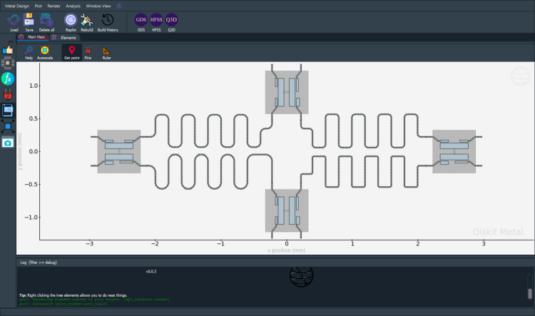
[14]:
gui.screenshot()
You can also create the components by directly passing the options you know the renderer will require, like so:
[15]:
q1.delete()
q2.delete()
q3.delete()
q4.delete()

q1 = TransmonPocket(design, 'Q1', options = dict(
    pos_x='+2.55mm', pos_y='+0.0mm', gds_cell_name='FakeJunction_02', skeleton_a_column_name='q1 skeleton 2', **options))
q2 = TransmonPocket(design, 'Q2', options = dict(
    pos_x='+0.0mm', pos_y='-0.9mm', orientation = '90', gds_cell_name='FakeJunction_02', skeleton_a_column_name='q2 skeleton 2', **options))
q3 = TransmonPocket(design, 'Q3', options = dict(
    pos_x='-2.55mm', pos_y='+0.0mm', gds_cell_name='FakeJunction_01', skeleton_a_column_name='q3 skeleton 2', **options))
q4 = TransmonPocket(design, 'Q4', options = dict(
    pos_x='+0.0mm', pos_y='+0.9mm', orientation = '90', gds_cell_name='my_other_junction', skeleton_a_column_name='q4 skeleton 2', **options))

design.qgeometry.tables['junction']
[15]:
| component | name | geometry | layer | subtract | helper | chip | width | hfss_inductance | hfss_capacitance | hfss_resistance | hfss_mesh_kw_jj | q3d_inductance | q3d_capacitance | q3d_resistance | q3d_mesh_kw_jj | gds_cell_name | skeleton_a_column_name | |
|---|---|---|---|---|---|---|---|---|---|---|---|---|---|---|---|---|---|---|
| 0 | 9 | rect_jj | LINESTRING (2.55000 -0.01500, 2.55000 0.01500) | 1 | False | False | main | 0.02 | 10nH | 0 | 0 | 0.000007 | 10nH | 0 | 0 | 0.000007 | FakeJunction_02 | q1 skeleton 2 |
| 1 | 10 | rect_jj | LINESTRING (0.01500 -0.90000, -0.01500 -0.90000) | 1 | False | False | main | 0.02 | 10nH | 0 | 0 | 0.000007 | 10nH | 0 | 0 | 0.000007 | FakeJunction_02 | q2 skeleton 2 |
| 2 | 11 | rect_jj | LINESTRING (-2.55000 -0.01500, -2.55000 0.01500) | 1 | False | False | main | 0.02 | 10nH | 0 | 0 | 0.000007 | 10nH | 0 | 0 | 0.000007 | FakeJunction_01 | q3 skeleton 2 |
| 3 | 12 | rect_jj | LINESTRING (0.01500 0.90000, -0.01500 0.90000) | 1 | False | False | main | 0.02 | 10nH | 0 | 0 | 0.000007 | 10nH | 0 | 0 | 0.000007 | my_other_junction | q4 skeleton 2 |
Can my user-defined renderer change/interact with the design?#
Accessing information and methods#
It is possible that the resoult of a renderering action, or analysis requires a design update back to qiskit-metal. This can be achieved wthout the user intervetion by simply controlling the QDesign instance from within the QRenderer.
Just as an example, the next three cells inspect the current design QComponent, QGeometry table, and QRenderer names.
[16]:
a_skeleton.design.components.keys()
[16]:
['cpw1', 'cpw2', 'cpw3', 'cpw4', 'Q1', 'Q2', 'Q3', 'Q4']
[17]:
a_skeleton.design.qgeometry.tables.keys()
[17]:
dict_keys(['path', 'poly', 'junction'])
[18]:
a_skeleton.design.renderers.keys()
[18]:
dict_keys(['hfss', 'q3d', 'gds', 'skeleton'])
The base QRenderer class comes with useful methods to more easily access some of the information. You will find more method described in the QRenderer documentation. The example below for example returns the QComponent’s IDs.
[19]:
a_skeleton.get_unique_component_ids(highlight_qcomponents = ['Q1', 'Q1', 'Q4', 'cpw1', 'cpw2', 'cpw3', 'cpw4'])
[19]:
([7, 5, 12, 8, 6, 9], 0)
The following instead shows three ways to access the same QGeometry table.
[20]:
a_skeleton.design.components['Q1'].qgeometry_table('junction') # via QComonent name
a_skeleton.design._components[9].qgeometry_table('junction') # via QComponent ID
q1.qgeometry_table('junction') # via the QComponent instance
[20]:
| component | name | geometry | layer | subtract | helper | chip | width | hfss_inductance | hfss_capacitance | hfss_resistance | hfss_mesh_kw_jj | q3d_inductance | q3d_capacitance | q3d_resistance | q3d_mesh_kw_jj | gds_cell_name | skeleton_a_column_name | |
|---|---|---|---|---|---|---|---|---|---|---|---|---|---|---|---|---|---|---|
| 0 | 9 | rect_jj | LINESTRING (2.55000 -0.01500, 2.55000 0.01500) | 1 | False | False | main | 0.02 | 10nH | 0 | 0 | 0.000007 | 10nH | 0 | 0 | 0.000007 | FakeJunction_02 | q1 skeleton 2 |
The method QSkeletonRenderer.get_qgeometry_tables_for_skeleton() exemplifies how to iterate through chips and tables.
[21]:
from tutorials.resources.skeleton_renderer import QSkeletonRenderer
?QSkeletonRenderer.get_qgeometry_tables_for_skeleton
Communicate state#
We can also interact with any other method of the QDesign instance, for example we can generate a warning into the logger as shown in the next cell. This is particularly useful to document problems with the user-defined QRenderer execution
[22]:
# Purposefully generates an warning message.
a_skeleton.logger.warning('Show a warning message for plugin developer.')
12:36PM 34s WARNING [<module>]: Show a warning message for plugin developer.
Qiskit Metal Version#
[23]:
metal.about();
Qiskit Metal        0.0.3

Basic
____________________________________
 Python              3.7.8 | packaged by conda-forge | (default, Nov 27 2020, 18:48:03) [MSC v.1916 64 bit (AMD64)]
 Platform            Windows AMD64
 Installation path   c:\workspace\qiskit-metal\qiskit_metal

Packages
____________________________________
 Numpy               1.19.5
 Qutip               4.5.3

Rendering
____________________________________
 Matplotlib          3.3.4

GUI
____________________________________
 PySide2 version     5.13.2
 Qt version          5.9.7
 SIP version         4.19.8

IBM Quantum Team
[24]:
# This command is below if the user wants to close the Metal GUI.
# gui.main_window.close()
For more information, review the Introduction to Quantum Computing and Quantum Hardware lectures below
|
Lecture Video | Lecture Notes | Lab |
|
Lecture Video | Lecture Notes | Lab |
|
Lecture Video | Lecture Notes | Lab |
|
Lecture Video | Lecture Notes | Lab |
|
Lecture Video | Lecture Notes | Lab |
|
Lecture Video | Lecture Notes | Lab |