Note
This page was generated from tut//1-Overview//1.2-Quick-start.ipynb.
Quick start#
For convenience, let’s begin by enabling automatic reloading of modules when they change.
[1]:
%load_ext autoreload
%autoreload 2
Import Qiskit Metal#
[2]:
import qiskit_metal as metal
from qiskit_metal import designs, draw
from qiskit_metal import MetalGUI, Dict, open_docs

%metal_heading Welcome to Qiskit Metal!
Welcome to Qiskit Metal!
My first Quantum Design (QDesign)#
A Quantum Design (QDesign) can be selected from the design library qiskit_metal.designs. All designs are children of the QDesign base class, which defines the basic funcationality of a QDesign.
We will start with the simple planar QDesign.
design = designs.DesignPlanar()
Interactivly view, edit, and simulate QDesign: Metal GUI#
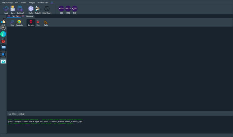
To launch the qiskit metal GUI,use the method MetalGUI.
gui = MetalGUI(design)
[3]:
design = designs.DesignPlanar()
gui = MetalGUI(design)
[4]:
gui.screenshot()
[5]:
%metal_heading Hello Quantum World!
Hello Quantum World!
My First Quantum Component (QComponent)#
We can create a ready-made and optimized transmon qubit form the QLibrary of components. Qubit qcomponents are stored in the library qiskit_metal.qlibrary.qubits. The file that contains the transmon pocket is called transmon_pocket, and the QComponent class inside it is TransmonPocket.
Let’s create a new qubit by creating an object of this class.
[6]:
# Select a QComponent to create (The QComponent is a python class named `TransmonPocket`)
from qiskit_metal.qlibrary.qubits.transmon_pocket import TransmonPocket

# Create a new qcomponent object with name 'Q1'
q1 = TransmonPocket(design, 'Q1')
gui.rebuild()  # rebuild the design and plot
[7]:
# save screenshot
gui.edit_component('Q1')
gui.autoscale()
gui.screenshot()
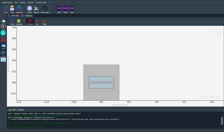
Let’s see what the Q1 object looks like
[8]:
q1
[8]:
name:    Q1
class:   TransmonPocket
options:
  'pos_x'             : '0um',
  'pos_y'             : '0um',
  'connection_pads'   : {
                        },
  'chip'              : 'main',
  'pad_gap'           : '30um',
  'inductor_width'    : '20um',
  'pad_width'         : '455um',
  'pad_height'        : '90um',
  'pocket_width'      : '650um',
  'pocket_height'     : '650um',
  'orientation'       : '0',
  'hfss_wire_bonds'   : False,
  'q3d_wire_bonds'    : False,
  'hfss_inductance'   : '10nH',
  'hfss_capacitance'  : 0,
  'hfss_resistance'   : 0,
  'hfss_mesh_kw_jj'   : 7e-06,
  'q3d_inductance'    : '10nH',
  'q3d_capacitance'   : 0,
  'q3d_resistance'    : 0,
  'q3d_mesh_kw_jj'    : 7e-06,
  'gds_cell_name'     : 'my_other_junction',
module:  qiskit_metal.qlibrary.qubits.transmon_pocket
id:      1
Parsed view of options
The QComponent comes with some default options. The options are used in the make function of the qcomponent to create the QGeometry you see in the plot above. * Options are parsed by Qiskit Metal. * You can change them from the gui or the script api.
[9]:
%metal_print How do I edit options? API or GUI
You can use the gui to create, edit, plot, modify, quantum components. Equivalently, you can also do everything form the python API. The GUI is just calling the API for you.
[10]:
# Change options
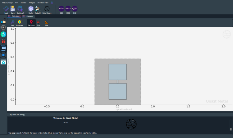
q1.options.pos_x = '0.5 mm'
q1.options.pos_y = '0.25 mm'
q1.options.pad_height = '225 um'
q1.options.pad_width = '250 um'
q1.options.pad_gap = '50 um'
# Update the geoemtry, since we changed the options
gui.rebuild()
[11]:
gui.autoscale()
gui.screenshot()
They are stored in design.components. It can be accessd as a dictionary (design.components['Q1']) or object (design.components.Q1).
[12]:
q1 = design.components['Q1']
[13]:
%metal_print Where are the default options?
A QComponent is created with default options. To find out what these are use QComponentClass.get_template_options(design)
[14]:
TransmonPocket.get_template_options(design)
[14]:
{'pos_x': '0um',
 'pos_y': '0um',
 'connection_pads': {},
 '_default_connection_pads': {'pad_gap': '15um',
  'pad_width': '125um',
  'pad_height': '30um',
  'pad_cpw_shift': '5um',
  'pad_cpw_extent': '25um',
  'cpw_width': 'cpw_width',
  'cpw_gap': 'cpw_gap',
  'cpw_extend': '100um',
  'pocket_extent': '5um',
  'pocket_rise': '65um',
  'loc_W': '+1',
  'loc_H': '+1'},
 'chip': 'main',
 'pad_gap': '30um',
 'inductor_width': '20um',
 'pad_width': '455um',
 'pad_height': '90um',
 'pocket_width': '650um',
 'pocket_height': '650um',
 'orientation': '0',
 'hfss_wire_bonds': False,
 'q3d_wire_bonds': False,
 'hfss_inductance': '10nH',
 'hfss_capacitance': 0,
 'hfss_resistance': 0,
 'hfss_mesh_kw_jj': 7e-06,
 'q3d_inductance': '10nH',
 'q3d_capacitance': 0,
 'q3d_resistance': 0,
 'q3d_mesh_kw_jj': 7e-06,
 'gds_cell_name': 'my_other_junction'}
[15]:
%metal_print How do I change the default options?
Now lets change the default options we will use to create the transmon
[16]:
# THIS ISN'T CHANGING THE DEFAULT OPTIONS - NEEDS UPDATE
q1.options.pos_x = '0.5 mm'
q1.options.pos_y = '250 um'

# Rebubild for changes to propagate
gui.rebuild()
[17]:
%metal_print How do I work with units? <br><br> (parse options and values)
(parse options and values)
Use the design.parse_value or QComponent.parse_value (such as q1.parse_value). The two functions serve the same purpose.
[18]:
print('Design default units for length: ', design.get_units())
print('\nExample 250 micron parsed to design units:', design.parse_value('0.250 um'),  design.get_units())

dictionary = {'key_in_cm': '1.2 cm', 'key_in_microns': '50 um'}
print('\nExample parse dict:', design.parse_value(dictionary))

a_list = ['1m', '1mm', '1um', '1 nm']
print('\nExample parse list:', design.parse_value(a_list))
Design default units for length:  mm

Example 250 micron parsed to design units: 0.00025 mm

Example parse dict: {'key_in_cm': 12.0, 'key_in_microns': 0.05}

Example parse list: [1000.0, 1, 0.001, 1.0000000000000002e-06]
[19]:
design.parse_value('2 * 2um')
[19]:
0.004
[20]:
design.parse_value('2um + 5um')
[20]:
0.007
[21]:
design.qgeometry.tables['junction']
[21]:
| component | name | geometry | layer | subtract | helper | chip | width | hfss_inductance | hfss_capacitance | hfss_resistance | hfss_mesh_kw_jj | q3d_inductance | q3d_capacitance | q3d_resistance | q3d_mesh_kw_jj | gds_cell_name | |
|---|---|---|---|---|---|---|---|---|---|---|---|---|---|---|---|---|---|
| 0 | 1 | rect_jj | LINESTRING (0.50000 0.22500, 0.50000 0.27500) | 1 | False | False | main | 0.02 | 10nH | 0 | 0 | 0.000007 | 10nH | 0 | 0 | 0.000007 | my_other_junction |
Can use python syntax inside options. Parse uses pythonic ast_eval.
[22]:
#### List
print('* '*10+' LIST '+'* '*10,'\n')
str_in = "[1,2,3,'10um']"
out = design.parse_value(str_in)
print(f'Parsed output:\n {str_in}  ->  {out} \n Out type: {type(out)}\n')

str_in = "['2*2um', '2um + 5um']"
out = design.parse_value(str_in)
print(f'Parsed output:\n {str_in}  ->  {out} \n Out type: {type(out)}\n')

#### Dict
print('* '*10+' DICT '+'* '*10,'\n')

str_in = "{'key1': '100um', 'key2': '1m'}"
out = design.parse_value(str_in)
print(f'Parsed output:\n {str_in}  ->  {out} \n Out type: {type(out)}\n')
* * * * * * * * * *  LIST * * * * * * * * * *

Parsed output:
 [1,2,3,'10um']  ->  [1, 2, 3, 0.01]
 Out type: <class 'list'>

Parsed output:
 ['2*2um', '2um + 5um']  ->  [0.004, 0.007]
 Out type: <class 'list'>

* * * * * * * * * *  DICT * * * * * * * * * *

Parsed output:
 {'key1': '100um', 'key2': '1m'}  ->  {'key1': 0.1, 'key2': 1000.0}
 Out type: <class 'addict.addict.Dict'>
How do I overwrite QComponents?#
To enable component overwrite of components with the same name, use the following cell
[23]:
design.overwrite_enabled = True
[24]:
%metal_heading Quantum pins: QPins!
Quantum pins: QPins!
The component designer can define pins. Pins can be used to link components together. For examaple, two transmon can each have a pin. The two pins can be connectoed by CPWs, as we will show below.
First, let us add pins to the transmon. We will add 4 pins called a, b, c, and d. Each pin will be at a differnet location (corner of the transmon), defined by the options loc_W and loc_H.
[25]:
from qiskit_metal.qlibrary.qubits.transmon_pocket import TransmonPocket

design.delete_all_components()

options = dict(
    pad_width = '425 um',
    pocket_height = '650um',
    connection_pads=dict(  # pin connecotrs
        a = dict(loc_W=+1,loc_H=+1),
        b = dict(loc_W=-1,loc_H=+1, pad_height='30um'),
        c = dict(loc_W=+1,loc_H=-1, pad_width='200um'),
        d = dict(loc_W=-1,loc_H=-1, pad_height='50um')
    )
)

q1 = TransmonPocket(design, 'Q1', options = dict(pos_x='+0.5mm', pos_y='+0.5mm', **options))
[26]:
# Take a screenshot with the component highlighted and the pins shown
gui.rebuild()
gui.autoscale()
gui.edit_component('Q1')
gui.zoom_on_components(['Q1'])
gui.highlight_components(['Q1'])
gui.screenshot()

To access a pin
[27]:
q1.pins.a
q1.pins['a']
[27]:
{'points': [array([0.925, 0.7  ]), array([0.925, 0.69 ])],
 'middle': array([0.925, 0.695]),
 'normal': array([1., 0.]),
 'tangent': array([0., 1.]),
 'width': 0.01,
 'gap': 0.006,
 'chip': 'main',
 'parent_name': 2,
 'net_id': 0,
 'length': 0}
If you have selected a QComponent, you can call the button that says edit source in the gui. Once selected, you could also call the same function from the code.
[28]:
gui.edit_component('Q1')
This will pop open a new source editor window, you can change the source on the fly. * Make sure you press the Rebuild component button in the source editor when you are ready to save and make your changes.
[29]:
%metal_heading My first quantum chip
My first quantum chip
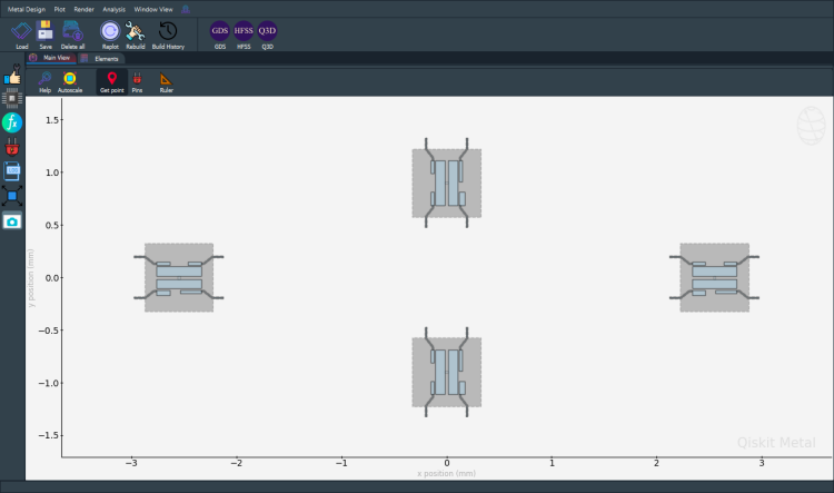
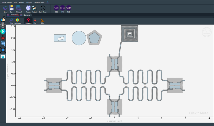
Creating a whole chip of qubit with connectors#
Let’s now create a a whole chip. In the following, you will pass options to create 4 transmons qubits in a ring. First let us clear all qcomponents in the design.
[30]:
design.delete_all_components()
gui.rebuild() # refresh
[31]:
from qiskit_metal.qlibrary.qubits.transmon_pocket import TransmonPocket

# Allow running the same cell here multiple times to overwrite changes
design.overwrite_enabled = True

## Custom options for all the transmons
options = dict(
    # Some options we want to modify from the deafults
    # (see below for defaults)
    pad_width = '425 um',
    pocket_height = '650um',
    # Adding 4 connectors (see below for defaults)
    connection_pads=dict(
        a = dict(loc_W=+1,loc_H=+1),
        b = dict(loc_W=-1,loc_H=+1, pad_height='30um'),
        c = dict(loc_W=+1,loc_H=-1, pad_width='200um'),
        d = dict(loc_W=-1,loc_H=-1, pad_height='50um')
    )
)

## Create 4 transmons

q1 = TransmonPocket(design, 'Q1', options = dict(
    pos_x='+2.55mm', pos_y='+0.0mm', **options))
q2 = TransmonPocket(design, 'Q2', options = dict(
    pos_x='+0.0mm', pos_y='-0.9mm', orientation = '90', **options))
q3 = TransmonPocket(design, 'Q3', options = dict(
    pos_x='-2.55mm', pos_y='+0.0mm', **options))
q4 = TransmonPocket(design, 'Q4', options = dict(
    pos_x='+0.0mm', pos_y='+0.9mm', orientation = '90', **options))

## Rebuild the design
gui.rebuild()
gui.autoscale()
[32]:
gui.toggle_docks(True)
gui.screenshot()
[33]:
%metal_heading Connecting QPins with coplanar waveguides (CPWs)
Connecting QPins with coplanar waveguides (CPWs)
Let’s import the basic cpw QComponent from the QLibrary. It is a class called RouteMeander. We can see its default options using RouteMeander.get_template_options(design)
[34]:
from qiskit_metal.qlibrary.tlines.meandered import RouteMeander
RouteMeander.get_template_options(design)
[34]:
{'pin_inputs': {'start_pin': {'component': '', 'pin': ''},
  'end_pin': {'component': '', 'pin': ''}},
 'fillet': '0',
 'lead': {'start_straight': '0mm',
  'end_straight': '0mm',
  'start_jogged_extension': '',
  'end_jogged_extension': ''},
 'total_length': '7mm',
 'chip': 'main',
 'layer': '1',
 'trace_width': 'cpw_width',
 'meander': {'spacing': '200um', 'asymmetry': '0um'},
 'snap': 'true',
 'prevent_short_edges': 'true',
 'hfss_wire_bonds': False,
 'q3d_wire_bonds': False}
We can now modify the options and connect all four qubits. Since this is repetative, you can define a function to wrap up the repetatvie steps. Here we will call this connect. This function creates a RouteMeander QComponent class.
[35]:
options = Dict(
meander=Dict(
lead_start='0.1mm',
lead_end='0.1mm',
asymmetry='0 um')
)
def connect(component_name: str, component1: str, pin1: str, component2: str, pin2: str,
length: str,
asymmetry='0 um', flip=False):
"""Connect two pins with a CPW."""
myoptions = Dict(
pin_inputs=Dict(
start_pin=Dict(
component=component1,
pin=pin1),
end_pin=Dict(
component=component2,
pin=pin2)),
lead=Dict(
start_straight='0.13mm'
),
total_length=length,
fillet = '90um')
myoptions.update(options)
myoptions.meander.asymmetry = asymmetry
myoptions.meander.lead_direction_inverted = 'true' if flip else 'false'
return RouteMeander(design, component_name, myoptions)
asym = 150
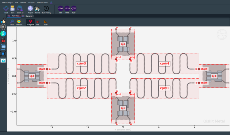
cpw1 = connect('cpw1', 'Q1', 'd', 'Q2', 'c', '6.0 mm', f'+{asym}um')
cpw2 = connect('cpw2', 'Q3', 'c', 'Q2', 'a', '6.1 mm', f'-{asym}um', flip=True)
cpw3 = connect('cpw3', 'Q3', 'a', 'Q4', 'b', '6.0 mm', f'+{asym}um')
cpw4 = connect('cpw4', 'Q1', 'b', 'Q4', 'd', '6.1 mm', f'-{asym}um', flip=True)
gui.rebuild()
gui.autoscale()
[36]:
gui.toggle_docks(True)
gui.highlight_components(['Q1','Q2','Q3','Q4','cpw1','cpw2','cpw3','cpw4'])
gui.screenshot()
[37]:
design.components.keys()
[37]:
['Q1', 'Q2', 'Q3', 'Q4', 'cpw1', 'cpw2', 'cpw3', 'cpw4']
We can access the created CPW from the design too.
[38]:
design.components.cpw2
[38]:
name:    cpw2
class:   RouteMeander
options:
  'pin_inputs'        : {
       'start_pin'         : {
            'component'         : 'Q3',
            'pin'               : 'c',
                             },
       'end_pin'           : {
            'component'         : 'Q2',
            'pin'               : 'a',
                             },
                        },
  'fillet'            : '90um',
  'lead'              : {
       'start_straight'    : '0.13mm',
       'end_straight'      : '0mm',
       'start_jogged_extension': '',
       'end_jogged_extension': '',
                        },
  'total_length'      : '6.1 mm',
  'chip'              : 'main',
  'layer'             : '1',
  'trace_width'       : 'cpw_width',
  'meander'           : {
       'spacing'           : '200um',
       'asymmetry'         : '-150um',
       'lead_start'        : '0.1mm',
       'lead_end'          : '0.1mm',
       'lead_direction_inverted': 'true',
                        },
  'snap'              : 'true',
  'prevent_short_edges': 'true',
  'hfss_wire_bonds'   : False,
  'q3d_wire_bonds'    : False,
  'trace_gap'         : 'cpw_gap',
  '_actual_length'    : '6.100000000000002 mm',
module:  qiskit_metal.qlibrary.tlines.meandered
id:      8
We can see all the pins
[39]:
%metal_heading Variables in options
Variables in options
Variables#
The design can have variables, which can be used in the component options.
[40]:
design.variables.cpw_width = '10um'
design.variables.cpw_gap = '6um'
gui.rebuild()
For example, we can all qubit pads using the variables.
[41]:
cpw1.options.lead.end_straight = '100um'
cpw2.options.lead.end_straight = '100um'
cpw3.options.lead.end_straight = '100um'
cpw4.options.lead.end_straight = '100um'
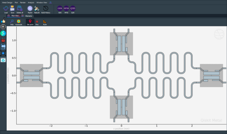
[42]:
# Set variables in the design
design.variables.pad_width = '450 um'
design.variables.cpw_width = '25 um'
design.variables.cpw_gap = '12 um'

# Assign variables to component options
q1.options.pad_width = 'pad_width'
q2.options.pad_width = 'pad_width'
q3.options.pad_width = 'pad_width'
q4.options.pad_width = 'pad_width'

# Rebuild all compoinent and refresh the gui
gui.rebuild()
gui.autoscale()
[43]:
gui.screenshot()
[44]:
%metal_heading Render to GDS
Render to GDS
[45]:
gds = design.renderers.gds
gds.options.path_filename
[45]:
'../resources/Fake_Junctions.GDS'
[46]:
gds.options.path_filename = './resources/Fake_Junctions.GDS'
[47]:
q1.options
[47]:
{'pos_x': '+2.55mm',
 'pos_y': '+0.0mm',
 'connection_pads': {'a': {'pad_gap': '15um',
   'pad_width': '125um',
   'pad_height': '30um',
   'pad_cpw_shift': '5um',
   'pad_cpw_extent': '25um',
   'cpw_width': 'cpw_width',
   'cpw_gap': 'cpw_gap',
   'cpw_extend': '100um',
   'pocket_extent': '5um',
   'pocket_rise': '65um',
   'loc_W': 1,
   'loc_H': 1},
  'b': {'pad_gap': '15um',
   'pad_width': '125um',
   'pad_height': '30um',
   'pad_cpw_shift': '5um',
   'pad_cpw_extent': '25um',
   'cpw_width': 'cpw_width',
   'cpw_gap': 'cpw_gap',
   'cpw_extend': '100um',
   'pocket_extent': '5um',
   'pocket_rise': '65um',
   'loc_W': -1,
   'loc_H': 1},
  'c': {'pad_gap': '15um',
   'pad_width': '200um',
   'pad_height': '30um',
   'pad_cpw_shift': '5um',
   'pad_cpw_extent': '25um',
   'cpw_width': 'cpw_width',
   'cpw_gap': 'cpw_gap',
   'cpw_extend': '100um',
   'pocket_extent': '5um',
   'pocket_rise': '65um',
   'loc_W': 1,
   'loc_H': -1},
  'd': {'pad_gap': '15um',
   'pad_width': '125um',
   'pad_height': '50um',
   'pad_cpw_shift': '5um',
   'pad_cpw_extent': '25um',
   'cpw_width': 'cpw_width',
   'cpw_gap': 'cpw_gap',
   'cpw_extend': '100um',
   'pocket_extent': '5um',
   'pocket_rise': '65um',
   'loc_W': -1,
   'loc_H': -1}},
 'chip': 'main',
 'pad_gap': '30um',
 'inductor_width': '20um',
 'pad_width': 'pad_width',
 'pad_height': '90um',
 'pocket_width': '650um',
 'pocket_height': '650um',
 'orientation': '0',
 'hfss_wire_bonds': False,
 'q3d_wire_bonds': False,
 'hfss_inductance': '10nH',
 'hfss_capacitance': 0,
 'hfss_resistance': 0,
 'hfss_mesh_kw_jj': 7e-06,
 'q3d_inductance': '10nH',
 'q3d_capacitance': 0,
 'q3d_resistance': 0,
 'q3d_mesh_kw_jj': 7e-06,
 'gds_cell_name': 'my_other_junction'}
gds.options.path_filename#
Need to give the correct path and filename that has gds formatted cells. An example is located in the repositary under resources directory. The cells are “junctions” that would be placed inside qubits. Fake_Junctions has three cells named: “Fake_Junction_01”, “Fake_Junction_02”, “my_other_junction”.
Example: When creating transmon the default_option for gds_cell_name is “my_other_junction”.
[48]:
gds.options.path_filename = "resources/Fake_Junctions.GDS"
[49]:
design.renderers.gds.export_to_gds("awesome_design.gds")
[49]:
1
[50]:
%metal_heading More QComponents
More QComponents
Basic and crazy shapes.
See their source code to see how to get started on a few simple examples.
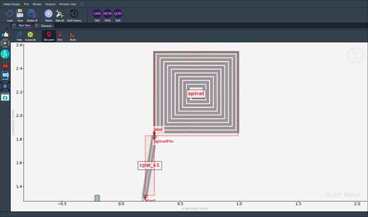
[51]:
from qiskit_metal.qlibrary.sample_shapes.n_square_spiral import NSquareSpiral
# print(NSquareSpiral.get_template_options(design))
ops = {
    'n': '10',
    'width': '10um',
    'radius': '100um',
    'gap': '22um',
    'pos_x': '0.65mm',
    'pos_y': '2.2mm',
    'orientation': '0',
    'subtract': 'False'}
NSquareSpiral(design, 'spiral', ops)
NSquareSpiral(design, 'spiral_cut', {**ops, **dict(subtract=True, width='22um', gap='10um')})
gui.rebuild()
To see source, try ??NSquareSpiral. Go to the actual source file and edit it, copy it, or edit it in the GUI using the Edit Source button.
[52]:
from qiskit_metal.qlibrary.tlines.straight_path import RouteStraight
# CpwStraightLine.get_template_options(design)
myoptions = Dict(
        pin_inputs=Dict(
            start_pin=Dict(
                component='Q4',
                pin='c'),
            end_pin=Dict(
                component='spiral',
                pin='spiralPin'))
        )


RouteStraight(design, 'cpw_s1', myoptions);
gui.rebuild()
[53]:
qcomponents = ['spiral', 'cpw_s1']
gui.highlight_components(qcomponents)
gui.zoom_on_components(qcomponents)
gui.screenshot()
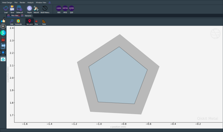
[54]:
from qiskit_metal.qlibrary.sample_shapes.n_gon import NGon
# display(NGon.get_template_options(design))
ops = {
    'n': '5',
    'radius': '250um',
    'pos_x': '-0.85mm',
    'pos_y': '2.0mm',
    'orientation': '15',
    'subtract': 'False',
    'helper': 'False',
    'chip': 'main',
    'layer': '1'}
NGon(design, 'ngon', ops)
NGon(design, 'ngon_negative', {**ops, **dict(subtract=True, radius='350um')})
gui.rebuild()
[55]:
gui.zoom_on_components(['ngon_negative'])
gui.screenshot()
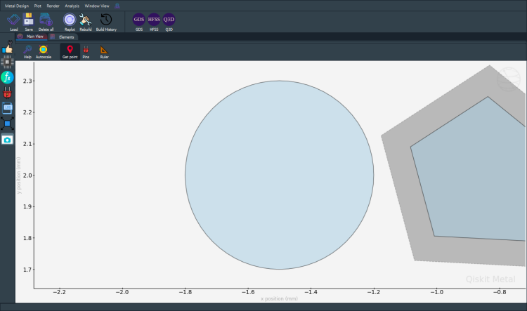
[56]:
from qiskit_metal.qlibrary.sample_shapes.circle_raster import CircleRaster
display(CircleRaster.get_template_options(design))

ops = { 'radius': '300um',
        'pos_x': '-1.5mm',
        'pos_y': '2mm',
        'resolution': '16',
        'cap_style': 'round',
        'subtract': 'False',
        'helper': 'False',
        'chip': 'main',
        'layer': '1'}
CircleRaster(design, 'CircleRaster', ops)
gui.rebuild()
{'radius': '300um',
 'pos_x': '0um',
 'pos_y': '0um',
 'resolution': '16',
 'cap_style': 'round',
 'subtract': 'False',
 'helper': 'False',
 'chip': 'main',
 'layer': '1'}
[57]:
gui.zoom_on_components(['CircleRaster'])
gui.screenshot()
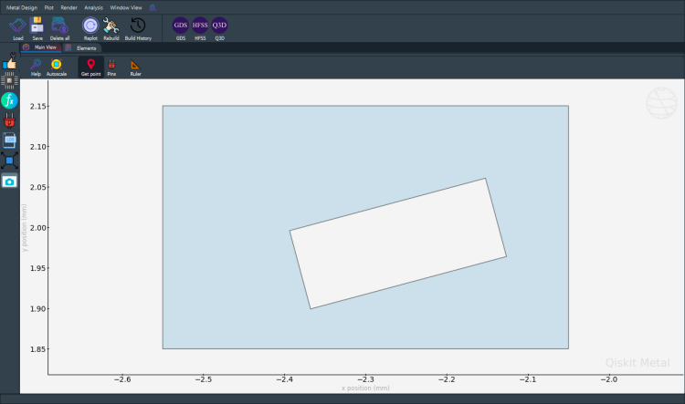
[58]:
from qiskit_metal.qlibrary.sample_shapes.rectangle_hollow import RectangleHollow
display(RectangleHollow.get_template_options(design))

ops = { 'width': '500um',
        'height': '300um',
        'pos_x': '-2.3mm',
        'pos_y': '2mm',
        'orientation': '0',
        'subtract': 'False',
        'helper': 'False',
        'chip': 'main',
        'layer': '1',
        'inner': {  'width': '250um',
                    'height': '100um',
                    'offset_x': '40um',
                    'offset_y': '-20um',
                    'orientation': '15'}}
RectangleHollow(design, 'RectangleHollow', ops)
gui.rebuild()
{'width': '500um',
 'height': '300um',
 'pos_x': '0um',
 'pos_y': '0um',
 'orientation': '0',
 'subtract': 'False',
 'helper': 'False',
 'chip': 'main',
 'layer': '1',
 'inner': {'width': '250um',
  'height': '100um',
  'offset_x': '40um',
  'offset_y': '-20um',
  'orientation': '15'}}
[59]:
gui.zoom_on_components(['RectangleHollow'])
gui.screenshot()
[60]:
gui.autoscale()
gui.screenshot()
[61]:
%metal_heading The geometry of QComponent: QGeometry
The geometry of QComponent: QGeometry
q1.qgeometry_bounds().[62]:
for name, qcomponent in design.components.items():
    print(f"{name:10s} : {qcomponent.qgeometry_bounds()}")
Q1         : [ 2.125 -0.325  2.975  0.325]
Q2         : [-0.325 -1.325  0.325 -0.475]
Q3         : [-2.975 -0.325 -2.125  0.325]
Q4         : [-0.325  0.475  0.325  1.325]
cpw1       : [ 0.2025     -0.63618364  2.125      -0.06881636]
cpw2       : [-2.125      -0.64243364 -0.2025     -0.06256636]
cpw3       : [-2.125       0.06881636 -0.2025      0.63618364]
cpw4       : [0.2025     0.06256636 2.125      0.64243364]
spiral     : [0.28  1.83  0.988 2.538]
spiral_cut : [0.28  1.83  0.988 2.538]
cpw_s1     : [0.2025 1.325  0.28   1.83  ]
ngon       : [-1.08339511  1.79033236 -0.60851854  2.24965738]
ngon_negative : [-1.17675315  1.7064653  -0.51192596  2.34952034]
CircleRaster : [-1.8  1.7 -1.2  2.3]
RectangleHollow : [-2.55  1.85 -2.05  2.15]
We can get all the QGeometry of a QComponent. There are several kinds, such as path and poly. Let us look at all the polygons used to create qubit q1
[63]:
q1.qgeometry_table('poly')
[63]:
| component | name | geometry | layer | subtract | helper | chip | fillet | |
|---|---|---|---|---|---|---|---|---|
| 0 | 3 | pad_top | POLYGON ((2.32500 0.01500, 2.77500 0.01500, 2.... | 1 | False | False | main | NaN |
| 1 | 3 | pad_bot | POLYGON ((2.32500 -0.10500, 2.77500 -0.10500, ... | 1 | False | False | main | NaN |
| 2 | 3 | rect_pk | POLYGON ((2.22500 -0.32500, 2.87500 -0.32500, ... | 1 | True | False | main | NaN |
| 3 | 3 | a_connector_pad | POLYGON ((2.65000 0.12000, 2.77500 0.12000, 2.... | 1 | False | False | main | NaN |
| 4 | 3 | b_connector_pad | POLYGON ((2.45000 0.12000, 2.32500 0.12000, 2.... | 1 | False | False | main | NaN |
| 5 | 3 | c_connector_pad | POLYGON ((2.57500 -0.12000, 2.77500 -0.12000, ... | 1 | False | False | main | NaN |
| 6 | 3 | d_connector_pad | POLYGON ((2.45000 -0.12000, 2.32500 -0.12000, ... | 1 | False | False | main | NaN |
Paths are lines. These can have a width.
[64]:
q1.qgeometry_table('path')
[64]:
| component | name | geometry | layer | subtract | helper | chip | width | fillet | hfss_wire_bonds | q3d_wire_bonds | |
|---|---|---|---|---|---|---|---|---|---|---|---|
| 0 | 3 | a_wire | LINESTRING (2.77500 0.13750, 2.80000 0.13750, ... | 1 | False | False | main | 0.025 | NaN | False | False |
| 1 | 3 | a_wire_sub | LINESTRING (2.77500 0.13750, 2.80000 0.13750, ... | 1 | True | False | main | 0.049 | NaN | False | False |
| 2 | 3 | b_wire | LINESTRING (2.32500 0.13750, 2.30000 0.13750, ... | 1 | False | False | main | 0.025 | NaN | False | False |
| 3 | 3 | b_wire_sub | LINESTRING (2.32500 0.13750, 2.30000 0.13750, ... | 1 | True | False | main | 0.049 | NaN | False | False |
| 4 | 3 | c_wire | LINESTRING (2.77500 -0.13750, 2.80000 -0.13750... | 1 | False | False | main | 0.025 | NaN | False | False |
| 5 | 3 | c_wire_sub | LINESTRING (2.77500 -0.13750, 2.80000 -0.13750... | 1 | True | False | main | 0.049 | NaN | False | False |
| 6 | 3 | d_wire | LINESTRING (2.32500 -0.13750, 2.30000 -0.13750... | 1 | False | False | main | 0.025 | NaN | False | False |
| 7 | 3 | d_wire_sub | LINESTRING (2.32500 -0.13750, 2.30000 -0.13750... | 1 | True | False | main | 0.049 | NaN | False | False |
Junction table holds information about Quantum juctions. Placement is defined by LineString and width.
[65]:
q1.qgeometry_table('junction')
[65]:
| component | name | geometry | layer | subtract | helper | chip | width | hfss_inductance | hfss_capacitance | hfss_resistance | hfss_mesh_kw_jj | q3d_inductance | q3d_capacitance | q3d_resistance | q3d_mesh_kw_jj | gds_cell_name | |
|---|---|---|---|---|---|---|---|---|---|---|---|---|---|---|---|---|---|
| 0 | 3 | rect_jj | LINESTRING (2.55000 -0.01500, 2.55000 0.01500) | 1 | False | False | main | 0.02 | 10nH | 0 | 0 | 0.000007 | 10nH | 0 | 0 | 0.000007 | my_other_junction |
[66]:
%metal_heading Qiskit Metal Version
Qiskit Metal Version
[67]:
metal.about();
Qiskit Metal        0.0.3

Basic
____________________________________
 Python              3.7.8 | packaged by conda-forge | (default, Nov 27 2020, 18:48:03) [MSC v.1916 64 bit (AMD64)]
 Platform            Windows AMD64
 Installation path   c:\workspace\qiskit-metal\qiskit_metal

Packages
____________________________________
 Numpy               1.19.5
 Qutip               4.5.3

Rendering
____________________________________
 Matplotlib          3.3.4

GUI
____________________________________
 PySide2 version     5.13.2
 Qt version          5.9.7
 SIP version         4.19.8

IBM Quantum Team
Can close Metal GUI from both notebook and GUI.
[68]:
# gui.main_window.close()
For more information, review the Introduction to Quantum Computing and Quantum Hardware lectures below
|
Lecture Video | Lecture Notes | Lab |
|
Lecture Video | Lecture Notes | Lab |
|
Lecture Video | Lecture Notes | Lab |
|
Lecture Video | Lecture Notes | Lab |
|
Lecture Video | Lecture Notes | Lab |
|
Lecture Video | Lecture Notes | Lab |